
How to build a racing game - curves
Sun, Jun 24, 2012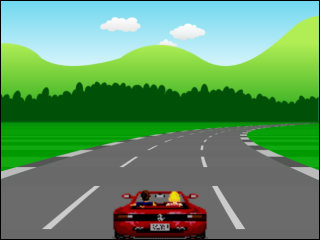
Earlier I published a simple outrun-style pseudo-3d racing game and followed up with an article showing how to get started with straight roads.
Today I’m going to go into more detail on how the curves work.
If you followed along with the previous article you will know that we built up our road geometry as an array of segments, each of which has world coordinates which get translated relative to the camera and then projected into the screen.
We only needed a z world coordinate for each point because, for straight roads, both x and y were zero.
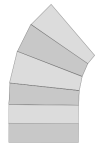
If we were building a full-blown 3d system we might implement curves by calculating x and z coordinates in a kind of fan-strip as shown on the left. However that kind of geometry can be a little complex to calculate and would require us to add a 3d rotation step to our projection equations…
… if we wanted to go down that path we would be better off using WebGL or its equivalent, but that’s not really what this project is about. We just want to use some old-school ‘good enough’ pseudo 3d tricks to fake our curves.
So you might be surprised to learn that we wont be calculating x coordinates for our road segments at all…
Instead we’ll follow Lou’s advice:
“To curve a road, you just need to change the position of the center-line in a curve shape… starting at the bottom of the screen, the amount that the center of the road shifts left or right steadily increases”
In our case, the center-line is the cameraX value we pass to the projection
calculations. This means that as we render() each segment of the road, we can
fake curves by offsetting the cameraX value by a steadily increasing amount.
In order to know how much to offset we need to store a curve value in each
segment. This value represents how much the segment should be offset from the
camera’s center line, and will be:
- negative for left hand curves
- positive for right hand curves
- smaller for easy curves
- larger for harder curves
The actual values are somewhat arbitrary, and through trial and error we can find good values to make our curves ‘feel’ right:
var ROAD = {
  LENGTH: { NONE: 0, SHORT:  25, MEDIUM:  50, LONG:  100 }, // num segments
  CURVE:  { NONE: 0, EASY:    2, MEDIUM:   4, HARD:    6 }
};
In addition to defining good curve values. We want to avoid any jarring
transitions when a straight turns into a curve (or vice versa) by easing
into and out of the curves. We do this by slowly incrementing (or decrementing) the
curve value for each segment until it reaches our desired value using traditional
easing functions such as:
easeIn:    function(a,b,percent) { return a + (b-a)*Math.pow(percent,2);                           },
easeOut:   function(a,b,percent) { return a + (b-a)*(1-Math.pow(1-percent,2));                     },
easeInOut: function(a,b,percent) { return a + (b-a)*((-Math.cos(percent*Math.PI)/2) + 0.5);        },
So now, given a function to add a single segment to our geometry…
function addSegment(curve) {
  var n = segments.length;
  segments.push({
     index: n,
        p1: { world: { z:  n   *segmentLength }, camera: {}, screen: {} },
        p2: { world: { z: (n+1)*segmentLength }, camera: {}, screen: {} },
     curve: curve,
     color: Math.floor(n/rumbleLength)%2 ? COLORS.DARK : COLORS.LIGHT
  });
}
… we can create a method to ease in, hold, and then ease out of a curved road:
function addRoad(enter, hold, leave, curve) {
  var n;
  for(n = 0 ; n < enter ; n++)
    addSegment(Util.easeIn(0, curve, n/enter));
  for(n = 0 ; n < hold  ; n++)
    addSegment(curve);
  for(n = 0 ; n < leave ; n++)
    addSegment(Util.easeInOut(curve, 0, n/leave));
}
… and we can layer additional geometry on top, such as S-Curves:
function addSCurves() {
  addRoad(ROAD.LENGTH.MEDIUM, ROAD.LENGTH.MEDIUM, ROAD.LENGTH.MEDIUM,  -ROAD.CURVE.EASY);
  addRoad(ROAD.LENGTH.MEDIUM, ROAD.LENGTH.MEDIUM, ROAD.LENGTH.MEDIUM,   ROAD.CURVE.MEDIUM);
  addRoad(ROAD.LENGTH.MEDIUM, ROAD.LENGTH.MEDIUM, ROAD.LENGTH.MEDIUM,   ROAD.CURVE.EASY);
  addRoad(ROAD.LENGTH.MEDIUM, ROAD.LENGTH.MEDIUM, ROAD.LENGTH.MEDIUM,  -ROAD.CURVE.EASY);
  addRoad(ROAD.LENGTH.MEDIUM, ROAD.LENGTH.MEDIUM, ROAD.LENGTH.MEDIUM,  -ROAD.CURVE.MEDIUM);
}
Changes to the update() method
The only changes we need to make to our existing update() method is to apply some
kind of centrifugal force to the car when its going around the curve.
We define an arbitrary multiplier that can be tuned until it ‘feels good’
var centrifugal = 0.3; // centrifugal force multiplier when going around curves
And we simply update the playerX position based on their current speed, the
current curve amount and the centrifugal force multiplier:
playerX = playerX - (dx * speedPercent * playerSegment.curve * centrifugal);
Rendering curves
Earlier we said we could render fake curves by offsetting the cameraX value
used in the projection calculations as we render() each segment of the road.
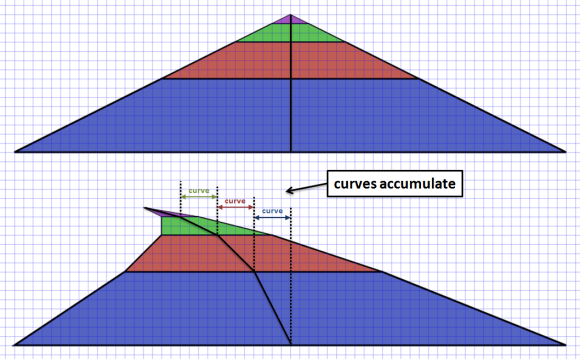
To do that we maintain an accumulating dx variable that increases by the
amount of curve for each segment, along with an x variable that will be
used as the offset to the cameraX value used in the projection calculations.
To implement curves we need to:
- offset each segments p1 projection by x
- offset each segments p2 projection by x + dx
- increase x by dx for the next segment
Finally, in order to avoid jarring transitions when crossing segment boundaries we must ensure dx is initialized with an interpolated value for the current base segments curve.
Modifying our render() method like so:
var baseSegment = findSegment(position);
var basePercent = Util.percentRemaining(position, segmentLength);
var dx = - (baseSegment.curve * basePercent);
var x  = 0;
for(n = 0 ; n < drawDistance ; n++) {

  ...

  Util.project(segment.p1, (playerX * roadWidth) - x,      cameraHeight, position - (segment.looped ? trackLength : 0), cameraDepth, width, height, roadWidth);
  Util.project(segment.p2, (playerX * roadWidth) - x - dx, cameraHeight, position - (segment.looped ? trackLength : 0), cameraDepth, width, height, roadWidth);

  x  = x + dx;
  dx = dx + segment.curve;

  ...
}
Hmmm. If I was brutally honest, I’d have to admit that this made a lot more sense when I was writing the code than it does now trying to explain it for others. Looking back now it looks suspiciously like I have a double accumulation going on and I can’t really justify the need for both x and dx ? That’s a terrible admission as a programmer!!… You know what, forget I said anything, there’s nothing to see here, pretend you didn’t read this note and lets move on…
UPDATE. Thanks to PeteB in comments below for reminding me that a curve is a 2nd order equation, and that I do need to maintain a separate dx as the rate of change of x. I started second guessing myself when writing this article, and I was also in a dazed and confused state of mind due to England getting knocked out of Euro2012 - on penalties - AGAIN! So its ok, there was nothing to worry about, this code is correct (at least as correct as a ‘fake’ curve can be!)
Parallax scrolling background
Finally, we need to scroll the parallax background layers by maintaining an offset for each layer…
var skySpeed    = 0.001; // background sky layer scroll speed when going around curve (or up hill)
var hillSpeed   = 0.002; // background hill layer scroll speed when going around curve (or up hill)
var treeSpeed   = 0.003; // background tree layer scroll speed when going around curve (or up hill)
var skyOffset   = 0;     // current sky scroll offset
var hillOffset  = 0;     // current hill scroll offset
var treeOffset  = 0;     // current tree scroll offset
… and increasing it during update() based on the curve of the players current segment and their speed…
skyOffset  = Util.increase(skyOffset,  skySpeed  * playerSegment.curve * speedPercent, 1);
hillOffset = Util.increase(hillOffset, hillSpeed * playerSegment.curve * speedPercent, 1);
treeOffset = Util.increase(treeOffset, treeSpeed * playerSegment.curve * speedPercent, 1);
… and then use that offset when we render() the background layers
Render.background(ctx, background, width, height, BACKGROUND.SKY,   skyOffset);
Render.background(ctx, background, width, height, BACKGROUND.HILLS, hillOffset);
Render.background(ctx, background, width, height, BACKGROUND.TREES, treeOffset);
Conclusion
So there you have it, fake psuedo-3d curves:

Most of the code we added for curves revolves around constructing the road geometry with the
appropriate curve value. Once we have that, providing a centrifugal force during update()
is easy.
Rendering the curves is only a few lines of code, but they can be conceptually hard to understand (and describe) exactly what’s happening. There are many approaches to faking curves and its easy to go down some dead ends, and even easier to get side tracked trying to do the ‘correct’ thing and before you know it you are implementing a full blown 3d system with matrices, rotation and true 3-d geometry… which I’ve already said is not the point here.
In writing this article I’m pretty sure that I actually have some problems with my curve implementation. In trying to visualize the algorithm for this article I can’t help but wonder why I need 2 accumulating values dx and x instead of just one… and if I’m not able to fully explain it then something, somewhere is wrong…
… but my time on this ‘weekend’ (ha!) project is pretty much up and, to be honest, the curves look pretty good to me - and really that’s what matters at the end of the day.
Next up, I’ll detail how the hills work. I’m pretty sure I remember how those work because they are actually true 3d height projections, no magic fakery going on there.
Until next time…
Related Links
- read more about v1 - straight roads
- read more about v2 - curves
- read more about v3 - hills
- read more about v4 - final
- read Lou’s Pseudo 3d Page
- view the source code
or you can play…
- the straight road demo
- the curves demo
- the hills demo
- the final version